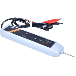
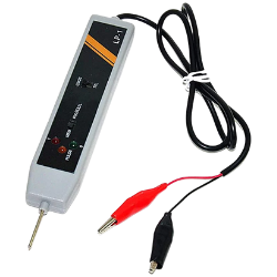
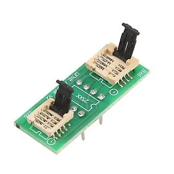
Digital Logic Probe
Inhouse product
-
 ৳12,300.00
৳13,500.00 -
৳688,500.00
৳1,100,000.00 -
৳259,500.00
৳400,000.00

Before joining the group buy, please keep in mind the following:
- Group buy requires a minimum of 1 Orders
- Group buy price is ৳2120.00.
- Your payment will be charged right after the group is completed.
- The product will be delivered within 10 days after the group completion. But the delivery date could be extended.
- Ensure you are aware of the group buy terms and conditions before joining.
Reviews & Ratings
About this item
- We are a professional supplier of integrated circuits and electronic components. Simply search for keywords in our shop. I believe you can find the products you need.
- Our products have undergone rigorous testing with high accuracy and good stability before leaving the factory. Please rest assured to use them.
- If you have any questions, please feel free to contact me. We will reply to you within 24 hours.
Descriptions:
- Connect the RED clip to the + connector and the BLACK clip to the connection of the power source of the circuit under testing. The supply voltage should not exceed 18V DC.
- For TTL and DTL, set the top selector switch to the side marked "TTL". For COMS, set the top selector switch to the side marked "CMOS". Contact the probe pin to the point to be tested. The LEDs indicate their logical states:
A: All LEDs are off – high impedance.
B: RED LED ON ------ HIGH CONDITION [1]
C: GREEN LED ON --- LOW CONDITION [0]
D: ORANGE LED ON - PULS.
- To detect and store pulses or level transitions, place the lower selector button on the page marked "PULSE" first. Contact the probe pin to the point to be tested. The LEDs indicate their basic state. If you place the lower selector switch on the side marked "MEM", the orange LED will light up when a pulse or level change is detected. The pulse direction can be determined compared to the original ground state. After use, reset the logic probe by resetting the lower selection switch to the side marked "PULSE".
Frequently Bought Products
Product Queries (0)
Login Or Registerto submit your questions to seller
Other Questions
No none asked to seller yet
-
৳12,300.00
৳13,500.00 -
৳688,500.00
৳1,100,000.00 -
৳259,500.00
৳400,000.00